 English
 Español


 Tel : +86-18565811709
 Email :
 -
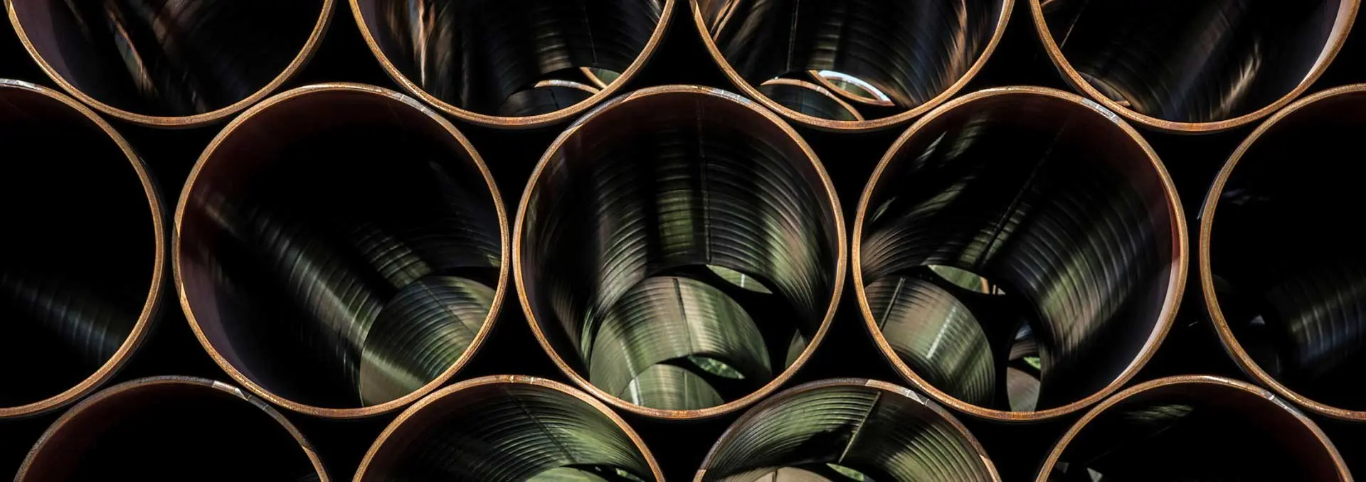
Carbon Steel Pipe
LSAW Steel Pipe
SSAW Steel Pipe
ERW Steel Pipe
Rolled And Welded Pipe
Piling Pipe
-
Seamless steel series
Seamless Steel Pipe
APL5L Line Pipe
Boiler steel pipe
Finned Tube
Pin Tube
Seamlss Honed steel pipe
-
Oilfield Tubular Goods
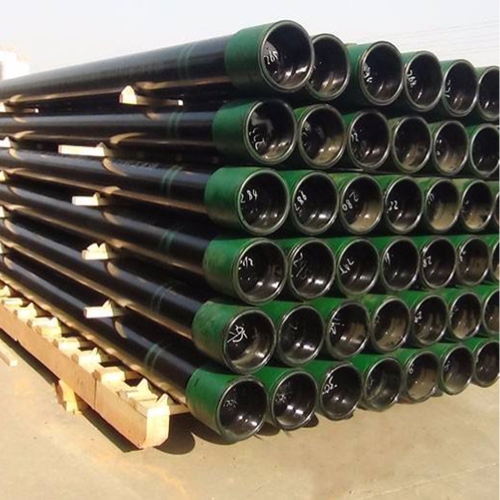
Casing and Tubing steel pipe
Slotted Pipe
Drill Pipe And Drill Collar
Pup Joint
Coupling
-
Alloy Steel Pipe
Alloy Seamless Steel Pipe
Alloy Welded Steel Pipe
Nickel Alloy Pipe
Monel Alloy Pipe
Inconel Alloy Pipe
Hastelloy alloy pipe
Copper Nickel alloy steel Pipe
-
Coated Steel Pipe
FBE Coated Pipe
Epoxy Coated Pipe
3LPE Coated Pipe
Concrete Coated Pipe
Galvanized Steel Pipe
Ceramic lined Pipe
Rubber lined Pipe
-
Stainless Steel Pipe
Stainless Steel Seamless Pipe
Stainless Steel Welded Pipe
Stainless Steel Screen Pipe
Stainless Hollow Section
Stainless Rectangular Hollow Section
Stainless Steel Plate
Duplex Stainless Steel Tube
Stainless Steel Coil
-
Pipe Fittings
Valve
Flanges/elbow/tee/cap/reducer
Prefabricated piping spools
-
Structural steel
Steel Sheet Pile
H Section
H/U/I Beam
Flat & Angle Bar
C Channel
-
Steel Plate
Carbon Steel Plate
Stainless Steel Plate
Aluminum Steel Plate
-
Steel Hollow Section
Square steel pipe
Rectangular steel pipe
Circular hollow section
-
Steel Structure Fabrication
Steel Structural Support Frames Backbone
Box Steel Components Steel Structure
Sustainable Prefab Steel
Steel Box Section Structural
Structural Steel Roof Truss Systems
Stud Welded Steel Column Structure