Description
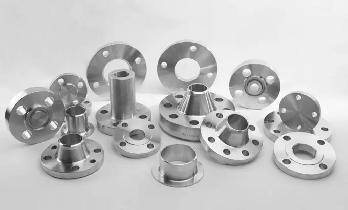
flange Size Range: 1/2” - 120” ( DN 15 - DN 3000)
Rating: 150, 300, 400, 600, 900, 1500, 2500;
Type: Welding Neck, Long Welding neck, Slip on, Blind, Spectacle Blind,
Lap joint, Socket weld, Threaded, Orifice, Ring Joint Flange,
Spacer and Blank, Anchor Flange, API flange, etc.
Standard: ANSI B16.5, ANSI B16.47 Series A & Series B, AWWA C207, BS4504,
BS3293, DIN EN1092-1, API590, JIS/KS, ISO 7005-1, JB/T, etc.
Material: Carbon steel, Low Temperature Carbon Steel, High Yield Carbon Steel,
Plate Material, Low Alloy Steel, Stainless Steel, Duplex Stainless Steel.
C.S: A36, A105, A266 CL2/CL4, ST37.2, C22.8, S235JR, S355JR;
LTCS: A350 LF2 CL1/CL2/LF3;
HYCS: A694 F42/F52/F60/F62/F65/F70;
Plate: A515 Gr60/70, A516 Gr 60/70, A285 Gr A B C, A240 304, A240 316
LAS: A182 F5, F9, F11 CL1/CL2/CL3, F12 CL1/CL2, F22 CL1/CL3, F91
SS: A182 F304/L, F304H, F316/L, F317/L, F44
Duplex SS: A182 F51/UNS 31803, F53/UNS 32750
Application: Can be widely used in the field of Gas, Oil, Pipeline,Water Supply, Electricity and Machinery.
|
Welding Neck Flange
Weld Neck Flange features a neck extension and weld bevel. Provides a natural form connection ideal for larger, high-pressure applications.
|
|
Blind Flange
Blind Flange has no bore or inner diameter. They are often altered to include NPT threads or custom bore holes to function as hubless Slip On flanges.
|
|
Lap Joint Flange
Lap Joint Flanges are intended to saddle over a stub end fitting. They feature an extended hub and a machined radius at the base of the flat face.
|
|
Slip On Flange
Slip On Flange is designed to accept the pipe into the center/bore, allowing welding around the outer diameter of the pipe.
|
|
Socket Weld Flange
Socket Weld types have a socket to insert pipe when space limitations make Weld Neck flanges difficult to use.
|
|
Threaded Flange
Threaded Flanges contain a female NPT threaded center for connection to male threaded piping. These flanges are commonly implemented in reducing connections.
|
Elbow
Product Specification:
Type: Seamless / Welded
Size Range: 1/2” - 24” ( DN 21.3 - DN 610) for Seamless;
26” - 96” ( DN 660 - DN 2438.4) for Welded.
Wall Thickness: SCH 5S - XXS
Style: Long Radius (LR) / Short Radius (SR)
Angle: 45 Degree, 90 Degree, 180 Degree or in specified degree.
Standard:
ASME/ANSI B16.9, ASME B16.28, MSS SP43, DIN2605, DIN2617, DIN2516, JISB2311, etc.
Application:
Can be widely used in the field of Chemical, Construction, Water Supply, Drainage, Oil, Light & Heavy Industries, Freezing, Sanitation, Fire Control, Electric Power, Aerospace, shipbuilding, etc.
Bend
Product Specification:
Type: Seamless / Welded
Size Range: 1/2” - 24” ( DN 21.3 - DN 610) for Seamless;
26” - 80”( DN 660 - DN 2032) for Welded.
Wall Thickness: SCH 10 - XXS
Style: R=3D R=5D R=7D R=10D or specified Radius
Angle: From 30 to 180 Degree or in specified degree.
Standard:
ASME B31.4, ASME 31.8, ASME B16.49, JIS, DIN, GB, HG, SH, JB, HGJ, etc.
Material:
Carbon steel, Low Temperature Carbon Steel, High Yield Carbon Steel, Alloy Steel, Stainless Steel.
C.S: ASTM/ASME A234 WPB / WPC, ST37.0, ST35.8, ST45.8
LTCS: A420 WPL6, ASTM/ASME A402 WPL3 / WPL6
HYCS: ASTM/ASME A860 WPHY 42 / 46 / 52 / 60 / 65 / 70
AS: ASTM/ASME A234 WP1 / WP12 / WP11 / WP22 / WP5 / WP9 / WP91 / 15Mo3 / 15CrMoV / 35CrMoV
SS: ASTM/ASME A403 WP304 / 304L / 304H / 304LN / 304N / 316L / 316H 321H / 347H
Cap
Size:
NPS from 1/2'' to 48'', DN from 12 to 1200,WT: 2-80mm, SCH 40/80/XXS
Material:
Carbon Steel --- ASTM A234 WPB ANSI B 16.9, DIN 2606 N-5 ST.37.0;
Stainless Steel --- ASTM 403 304/304L, 316/316L,316Ti,321,317L,310S;
Alloy Steel --- ASTM A234 WP 1/5/9/11/12/22/91
Bend Radius: 2.5D/3D/4D/5D/6D/7D/8D/9D/10D
Reducer
Outside Diameter:
Seamless Pipe Tee ( 1/2″~24″), ERW / Welded / Fabricated Pipe Tee (1/2″~48″)
Types: Concentric Reducers, Eccentric Reducers
Wall Thickness: 3mm – 40mm / SCH5, SCH10, SCH20, SCH30, SCH40,
STD, SCH80, XS, SCH60, SCH80, SCH120, SCH140, SCH160, XXS
Tee
Product Specification:
Type: Seamless / Welded
Size Range: 1/2” - 24” ( DN 21.3 - DN 610) for Seamless;
26” - 72” ( DN 660 - DN 1828.8) for Welded
Wall Thickness: SCH 20 - XXS
Style: Equal / Reducing
Process: Cold-Extruded / Hot-Pressed
Standard:
ASME/ANSI B16.9, GB/T12459, GB/T13401, DIN 2615, SH3408,
SH3409-96, SH3410-96, HG/T21635, DL/T 695, SY/T 0510, etc.
Sockolet
Sockolet have a socket into which a plain end. branch pipe is inserted, then fillet welded together. It is a type of self-reinforced branch fitting.
Dimensions:
Standard: MSS SP-97
Size: 1/4 to 4 Inch / DN6 to DN100
Pressure: 3000 LB and 6000LB
Alloy Steel: ASTM A182 F1, F5, F9, F11, F12, F22, F91
Carbon Steel: ASTM A105, A350 LF2,LF3. A694 F52, F60, F65, F70
Stainless Steel: ASTM A182 F304, F316, F317, F321, F310
Duplex Stainless Steel: ASTM A182 F51, F53, F55
Lap Joint Stub Ends
Size range: 1/2” to 36”
Grade: ASME/ASTM SA A234
Type: Long and short lap joint stub ends
Wall Thickness: Schedule 5s, 10s, 20s, Sch10, Sch20, Sch30, STD, Sch40 and etc.
standard of stub end:
ASME/ANSI B16.9, ASME B16.28, MSS-SP-43, ASTM A234, ASME SA234 WPB ,
WPBW, WPHY 42, WPHY 46, WPHY 52, WPH 60, WPHY 65 & WPHY 70.
Specification
|
CLASS 150 According to ASTM A/SA-105; ANSI B16.5
|
|
Nominal
Pipe
Size
|
Outside
Diam. of
Flange (O)
|
Thick.
of
Flange (C)
|
Diam.
of
Raised Face (R)
|
Diam.
of Hub
at Base (X)
|
Length
thru Hub
(Y)
|
Min.
Thread
Length
(T)
|
Min.
Counter
Bore (Q)
|
No. of
Holes
|
Diam. of
Holes
|
Diam. of
Bolts
|
Diam.
of Bolt
Circle
|
Approx.
Weight
(in Pounds)
|
|
½
|
3.5
|
0.44
|
1.38
|
1.19
|
0.62
|
0.62
|
—
|
4
|
0.62
|
0.5
|
2.38
|
1
|
|
¾
|
3.88
|
0.5
|
1.69
|
1.5
|
0.62
|
0.62
|
—
|
4
|
0.62
|
0.5
|
2.75
|
2
|
|
1
|
4.25
|
0.56
|
2
|
1.94
|
0.69
|
0.69
|
—
|
4
|
0.62
|
0.5
|
3.12
|
2
|
|
1 ¼
|
4.62
|
0.62
|
2.5
|
2.31
|
0.81
|
0.81
|
—
|
4
|
0.62
|
0.5
|
3.5
|
3
|
|
1 ½
|
5
|
0.69
|
2.88
|
2.56
|
0.88
|
0.88
|
—
|
4
|
0.62
|
0.5
|
3.88
|
3
|
|
2
|
6
|
0.75
|
3.62
|
3.06
|
1
|
1
|
—
|
4
|
0.75
|
0.62
|
4.75
|
5
|
|
2 ½
|
7
|
0.88
|
4.12
|
3.56
|
1.12
|
1.12
|
—
|
4
|
0.75
|
0.62
|
5.5
|
7
|
|
3
|
7.5
|
0.94
|
5
|
4.25
|
1.19
|
1.19
|
—
|
4
|
0.75
|
0.62
|
6
|
8
|
|
3 ½
|
8.5
|
0.94
|
5.5
|
4.81
|
1.25
|
1.25
|
—
|
8
|
0.75
|
0.62
|
7
|
11
|
|
4
|
9
|
0.94
|
6.19
|
5.31
|
1.31
|
1.31
|
—
|
8
|
0.75
|
0.62
|
7.5
|
13
|
|
5
|
10
|
0.94
|
7.31
|
6.44
|
1.44
|
1.44
|
—
|
8
|
0.88
|
0.75
|
8.5
|
15
|
|
6
|
11
|
1
|
8.5
|
7.56
|
1.56
|
1.56
|
—
|
8
|
0.88
|
0.75
|
9.5
|
19
|
|
8
|
13.5
|
1.12
|
10.62
|
9.69
|
1.75
|
1.75
|
—
|
8
|
0.88
|
0.75
|
11.75
|
30
|
|
10
|
16
|
1.19
|
12.75
|
12
|
1.94
|
1.94
|
—
|
12
|
1
|
0.88
|
14.25
|
43
|
|
12
|
19
|
1.25
|
15
|
14.38
|
2.19
|
2.19
|
—
|
12
|
1
|
0.88
|
17
|
64
|
|
14
|
21
|
1.38
|
16.25
|
15.75
|
2.25
|
2.25
|
—
|
12
|
1.12
|
1
|
18.75
|
90
|
|
16
|
23.5
|
1.44
|
18.5
|
18
|
2.5
|
2.5
|
—
|
16
|
1.12
|
1
|
21.25
|
98
|
|
18
|
25
|
1.56
|
21
|
19.88
|
2.69
|
2.69
|
—
|
16
|
1.25
|
1.13
|
22.75
|
130
|
|
20
|
27.5
|
1.69
|
23
|
22
|
2.88
|
2.88
|
—
|
20
|
1.25
|
1.12
|
25
|
165
|
|
24
|
32
|
1.88
|
27.25
|
26.12
|
3.25
|
3.25
|
—
|
20
|
1.38
|
1.25
|
29.5
|
220
|
|
CLASS 300 According to ASTM A/SA-105; ANSI B16.5
|
|
Nominal
Pipe
Size
|
Outside
Diam. of
Flange (O)
|
Thick.
of
Flange (C)
|
Diam.
of
Raised Face
(R)
|
Diam.
of Hub
at Base
(X)
|
Length
thru Hub
(Y)
|
Min.
Thread
Length
(T)
|
Min.
Counter Bore
(Q)
|
No. of
Holes
|
Diam. of
Holes
|
Diam.
of Bolts
|
Diam.
of Bolt
Circle
|
Approx.
Weight
(in Pounds)
|
|
1/2
|
3.75
|
0.56
|
1.38
|
1.5
|
0.88
|
0.62
|
0.93
|
4
|
0.62
|
0.5
|
2.62
|
2
|
|
3/4
|
4.62
|
0.62
|
1.69
|
1.88
|
1
|
0.62
|
1.14
|
4
|
0.75
|
0.62
|
3.25
|
3
|
|
1
|
4.88
|
0.69
|
2
|
2.12
|
1.06
|
0.69
|
1.41
|
4
|
0.75
|
0.62
|
3.5
|
3
|
|
1 1/4
|
5.25
|
0.75
|
2.5
|
2.5
|
1.06
|
0.81
|
1.75
|
4
|
0.75
|
0.62
|
3.88
|
4
|
|
1 1/2
|
6.12
|
0.81
|
2.88
|
2.75
|
1.19
|
0.88
|
1.99
|
4
|
0.88
|
0.75
|
4.5
|
6
|
|
2
|
6.5
|
0.88
|
3.62
|
3.31
|
1.31
|
1.12
|
2.5
|
8
|
0.75
|
0.62
|
5
|
7
|
|
2 1/2
|
7.5
|
1
|
4.12
|
3.94
|
1.5
|
1.25
|
3
|
8
|
0.88
|
0.75
|
5.88
|
10
|
|
3
|
8.25
|
1.12
|
5
|
4.62
|
1.69
|
1.25
|
3.63
|
8
|
0.88
|
0.75
|
6.62
|
13
|
|
3 1/2
|
9
|
1.19
|
5.5
|
5.25
|
1.75
|
1.44
|
4.13
|
8
|
0.88
|
0.75
|
7.25
|
17
|
|
4
|
10
|
1.25
|
6.19
|
5.75
|
1.88
|
1.44
|
4.63
|
8
|
0.88
|
0.75
|
7.88
|
22
|
|
5
|
11
|
1.38
|
7.31
|
7
|
2
|
1.69
|
5.69
|
8
|
0.88
|
0.75
|
9.25
|
28
|
|
6
|
12.5
|
1.44
|
8.5
|
8.12
|
2.06
|
1.81
|
6.75
|
12
|
0.88
|
0.75
|
10.62
|
39
|
|
8
|
15
|
1.62
|
10.62
|
10.25
|
2.44
|
2
|
8.75
|
12
|
1
|
0.88
|
13
|
58
|
|
10
|
17.5
|
1.88
|
12.75
|
12.62
|
2.62
|
2.19
|
10.88
|
16
|
1.12
|
1
|
15.25
|
81
|
|
12
|
20.5
|
2
|
15
|
14.75
|
2.88
|
2.38
|
12.94
|
16
|
1.25
|
1.12
|
17.75
|
115
|
|
14
|
23
|
2.12
|
16.25
|
16.75
|
3
|
2.5
|
14.19
|
20
|
1.25
|
1.12
|
20.25
|
165
|
|
16
|
25.5
|
2.25
|
18.5
|
19
|
3.25
|
2.69
|
16.19
|
20
|
1.38
|
1.25
|
22.5
|
190
|
|
18
|
28
|
2.38
|
21
|
21
|
3.5
|
2.75
|
18.19
|
24
|
1.38
|
1.25
|
24.75
|
250
|
|
20
|
30.5
|
2.5
|
23
|
23.12
|
3.75
|
2.88
|
20.19
|
24
|
1.38
|
1.25
|
27
|
315
|
|
24
|
36
|
2.75
|
27.25
|
27.62
|
4.19
|
3.25
|
24.19
|
24
|
1.62
|
1.5
|
32
|
475
|
|
CLASS 600 According to ASTM A/SA-105; ANSI B16.5
|
|
Nominal
Pipe
Size
|
Outside
Diam. of
Flange (O)
|
Thick.
of
Flange
(C)
|
Diam.
of
Raised Face
(R)
|
Diam.
of Hub
at Base (X)
|
Length
thru Hub
(Y)
|
Min.
Thread
Length
(T)
|
Min.
Counter
Bore
(Q)
|
No. of
Holes
|
Diam. of
Holes
|
Diam. of
Bolts
|
Diam. of
Bolt Circle
|
Approx.
Weight
(in Pounds)
|
|
1/2
|
3.75
|
0.56
|
1.38
|
1.5
|
0.88
|
0.62
|
0.93
|
4
|
0.62
|
0.5
|
2.62
|
2
|
|
3/4
|
4.62
|
0.62
|
1.69
|
1.88
|
1
|
0.62
|
1.14
|
4
|
0.75
|
0.62
|
3.25
|
3
|
|
1
|
4.88
|
0.69
|
2
|
2.12
|
1.06
|
0.69
|
1.41
|
4
|
0.75
|
0.62
|
3.5
|
4
|
|
1 1/4
|
5.25
|
0.81
|
2.5
|
2.5
|
1.12
|
0.81
|
1.75
|
4
|
0.75
|
0.62
|
3.88
|
5
|
|
1 1/2
|
6.12
|
0.88
|
2.88
|
2.75
|
1.25
|
0.88
|
1.99
|
4
|
0.88
|
0.75
|
4.5
|
7
|
|
2
|
6.5
|
1
|
3.62
|
3.31
|
1.44
|
1.12
|
2.5
|
8
|
0.75
|
0.62
|
5
|
9
|
|
2 1/2
|
7.5
|
1.12
|
4.12
|
3.94
|
1.62
|
1.25
|
3
|
8
|
0.88
|
0.75
|
5.88
|
13
|
|
3
|
8.25
|
1.25
|
5
|
4.62
|
1.81
|
1.38
|
3.63
|
8
|
0.88
|
0.75
|
6.62
|
16
|
|
3 1/2
|
9
|
1.38
|
5.5
|
5.25
|
1.94
|
1.56
|
4.13
|
8
|
1
|
0.88
|
7.25
|
21
|
|
4
|
10.75
|
1.5
|
6.19
|
6
|
2.12
|
1.62
|
4.63
|
8
|
1
|
0.88
|
8.5
|
37
|
|
5
|
13
|
1.75
|
7.31
|
7.44
|
2.38
|
1.88
|
5.69
|
8
|
1.12
|
1
|
10.5
|
63
|
|
6
|
14
|
1.88
|
8.5
|
8.75
|
2.62
|
2
|
6.75
|
12
|
1.12
|
1
|
11.5
|
80
|
|
8
|
16.5
|
2.19
|
10.62
|
10.75
|
3
|
2.25
|
8.75
|
12
|
1.25
|
1.12
|
13.75
|
115
|
|
10
|
20
|
2.5
|
12.75
|
13.5
|
3.38
|
2.56
|
10.88
|
16
|
1.38
|
1.25
|
17
|
170
|
|
12
|
22
|
2.62
|
15
|
15.75
|
3.62
|
2.75
|
12.94
|
20
|
1.38
|
1.25
|
19.25
|
200
|
|
14
|
23.75
|
2.75
|
16.25
|
17
|
3.69
|
2.88
|
14.19
|
20
|
1.5
|
1.38
|
20.75
|
230
|
|
16
|
27
|
3
|
18.5
|
19.5
|
4.19
|
3.06
|
16.19
|
20
|
1.62
|
1.5
|
23.75
|
330
|
|
18
|
29.25
|
3.25
|
21
|
21.5
|
4.62
|
3.12
|
18.19
|
20
|
1.75
|
1.63
|
25.75
|
400
|
|
20
|
32
|
3.5
|
23
|
24
|
5
|
3.25
|
20.19
|
24
|
1.75
|
1.62
|
28.5
|
510
|
|
24
|
37
|
4
|
27.25
|
28.25
|
5.5
|
3.62
|
24.19
|
24
|
2
|
1.88
|
33
|
730
|
|
CLASS 900According to ASTM A/SA-105; ANSI B16.5
|
|
Nominal
Pipe
Size
|
Outside
Diam. of
Flange (O)
|
Thick.
of
Flange
(C)
|
Diam.
of
Raised Face
(R)
|
Diam.
of Hub
at Base
(X)
|
Length
thru Hub (Y)
|
Min.
Thread
Length
(T)
|
Min.
Counter
Bore
(Q)
|
No. of
Holes
|
Diam. of
Holes
|
Diam. of
Bolts
|
Diam. of
Bolt Circle
|
Approx.
Weight
(in Pounds)
|
|
1/2
|
4.75
|
0.88
|
1.38
|
1.5
|
1.25
|
0.88
|
0.93
|
4
|
0.88
|
0.75
|
3.25
|
4
|
|
3/4
|
5.12
|
1
|
1.69
|
1.75
|
1.38
|
1
|
1.14
|
4
|
0.88
|
0.75
|
3.5
|
5
|
|
1
|
5.88
|
1.12
|
2
|
2.06
|
1.62
|
1.12
|
1.41
|
4
|
1
|
0.88
|
4
|
8
|
|
1 1/4
|
6.25
|
1.12
|
2.5
|
2.5
|
1.62
|
1.19
|
1.75
|
4
|
1
|
0.88
|
4.38
|
9
|
|
1 1/2
|
7
|
1.25
|
2.88
|
2.75
|
1.75
|
1.25
|
1.99
|
4
|
1.12
|
1
|
4.88
|
12
|
|
2
|
8.5
|
1.5
|
3.62
|
4.12
|
2.25
|
1.5
|
2.5
|
8
|
1
|
0.88
|
6.5
|
25
|
|
2 1/2
|
9.62
|
1.62
|
4.12
|
4.88
|
2.5
|
1.88
|
3
|
8
|
1.12
|
1
|
7.5
|
36
|
|
3
|
9.5
|
1.5
|
5
|
5
|
2.12
|
1.62
|
3.63
|
8
|
1
|
0.88
|
7.5
|
26
|
|
4
|
11.5
|
1.75
|
6.19
|
6.25
|
2.75
|
1.88
|
4.63
|
8
|
1.25
|
1.12
|
9.25
|
53
|
|
5
|
13.75
|
2
|
7.31
|
7.5
|
3.12
|
2.12
|
5.69
|
8
|
1.38
|
1.25
|
11
|
83
|
|
6
|
15
|
2.19
|
8.5
|
9.25
|
3.38
|
2.25
|
6.75
|
12
|
1.25
|
1.12
|
12.5
|
110
|
|
8
|
18.5
|
2.5
|
10.62
|
11.75
|
4.00
|
2.50
|
8.75
|
12
|
1.5
|
1.38
|
15.5
|
170
|
|
10
|
21.5
|
2.75
|
12.75
|
14.5
|
4.25
|
2.81
|
10.88
|
16
|
1.5
|
1.38
|
18.5
|
245
|
|
12
|
24
|
3.12
|
15
|
16.5
|
4.62
|
3
|
12.94
|
20
|
1.5
|
1.38
|
21
|
325
|
|
14
|
25.25
|
3.38
|
16.25
|
17.75
|
5.12
|
3.25
|
14.19
|
20
|
1.62
|
1.5
|
22
|
400
|
|
16
|
27.75
|
3.5
|
18.5
|
20
|
5.25
|
3.38
|
16.19
|
20
|
1.75
|
1.63
|
24.25
|
425
|
|
18
|
31
|
4
|
21
|
22.25
|
6
|
3.5
|
18.19
|
20
|
2
|
1.88
|
27
|
600
|
|
20
|
33.75
|
4.25
|
23
|
24.5
|
6.25
|
3.62
|
20.19
|
20
|
2.12
|
2
|
29.5
|
730
|
|
24
|
41
|
5.5
|
27.25
|
29.5
|
8
|
4
|
24.19
|
20
|
2.62
|
2.5
|
35.5
|
1400
|
|
CLASS 1500 According to ASTM A/SA-105; ANSI B16.5
|
|
Nominal
Pipe
Size
|
Outside
Diam. of
Flange (O)
|
Thick.
of
Flange
(C)
|
Diam.
of
Raised Face
(R)
|
Diam.
of Hub
at Base
(X)
|
Length
thru Hub
(Y)
|
Min.
Thread
Length
(T)
|
Min.
Counter
Bore
(Q)
|
No. of
Holes
|
Diam. of
Holes
|
Diam. of
Bolts
|
Diam. of
Bolt Circle
|
Approx.
Weight
(in Pounds)
|
|
1/2
|
4.75
|
0.88
|
1.38
|
1.5
|
1.25
|
0.88
|
0.93
|
4
|
0.88
|
0.75
|
3.25
|
4
|
|
3/4
|
5.12
|
1
|
1.69
|
1.75
|
1.38
|
1
|
1.14
|
4
|
0.88
|
0.75
|
3.5
|
5
|
|
1
|
5.88
|
1.12
|
2
|
2.06
|
1.62
|
1.12
|
1.41
|
4
|
1
|
0.88
|
4
|
8
|
|
1 1/4
|
6.25
|
1.12
|
2.5
|
2.5
|
1.62
|
1.19
|
1.75
|
4
|
1
|
0.88
|
4.38
|
9
|
|
1 1/2
|
7
|
1.25
|
2.88
|
2.75
|
1.75
|
1.25
|
1.99
|
4
|
1.12
|
1
|
4.88
|
12
|
|
2
|
8.5
|
1.5
|
3.62
|
4.12
|
2.25
|
1.5
|
2.5
|
8
|
1
|
0.88
|
6.5
|
25
|
|
2 1/2
|
9.62
|
1.62
|
4.12
|
4.88
|
2.5
|
1.88
|
3
|
8
|
1.12
|
1
|
7.5
|
36
|
Standard
|
Standard
|
Specification
|
|
ASTM A105
|
Standard Specification for Carbon Steel Forgings for Piping Applications
|
|
ASTM A350
|
Standard Specification for Carbon and Low-Alloy Steel Forgings, Requiring Notch Toughness Testing for Piping Components
|
|
ASTM A182
|
Standard Specification for Forged or Rolled Alloy and Stainless Steel Pipe Flanges, Forged Fittings, and Valves and Parts for High-Temperature Service
|
|
ASTM A404
|
Specification for Forged or Rolled Alloy Steel Pip Flanges, Forged Fittings, and Valves and Parts Specially Heat Treated for High-Temperature Service (Withdrawn 1974)
|
|
ASTM A234
|
Standard Specification for Piping Fittings of Wrought Carbon Steel and Alloy Steel for Moderate and High Temperature Service
|
|
ASTM A420
|
Standard Specification for Piping Fittings of Wrought Carbon Steel and Alloy Steel for Low-Temperature Service
|
|
ASTM A403
|
Standard Specification for Wrought Austenitic Stainless Steel Piping Fittings
|
|
ASTM A694
|
Standard Specification for Carbon and Alloy Steel Forgings for Pipe Flanges, Fittings, Valves, and Parts for High-Pressure Transmission Service
|
Process
Packing


 English
 Español


 Tel : +86-18565811709
 Email :