Description
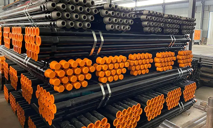
Drill Pipe Size:
OD: 60.32mm-168.28mm
WT: 6.45-12.7mm
LENGTH: R1, R2, R3
Heavy Weigh Drill Pipe
OD: 2-3/8" to 6-5/8"
LENGTH:,Range 2 and 3
Grades: E75, X95, G105, S135
Connection threads:NC26, NC31, NC38, NC40, NC46, NC50, 5 1/2FH.6 5/8FH.
Pipe Standard:API 5DP E75, X95, G105, S135
Upset Style:IU, EU, IEU
Connection:NC26, NC31, NC38, NC40, NC46, NC50, 5 1/2FH.6 5/8FH.
Application: Drill pipe is for exploration and development of oil and gas wells.
Drill Collars
- OD: 3 1/8"-11"
- Length: 30Ft / 31Ft / 43Ft / R1~R3
- Standard: API 5DP/API Spec 7-1 E75,X95,G105,S135
- Connection Type: NC, REG, FH, IF
- Thread: NC26, NC31, NC38, NC40, NC46, NC50,5.1 / 2FH
- Material: Stainless Steel / Alloy Steel /Carbon Steel / 4145H
- Classification: Non Magnetic Drill Collar, Slick Drill Collar, Spiral Drill Collar,Square Drill Collars, Monel Drill Collar, Pony Drill Collar, Spesifikasi Drill Collar
Application
- Oil And Gas Well Drilling
- Oilfield Drilling
- Mine Blasting
- Water Well Drilling
- Geothermal Wells Drilling
- Fore Poling
- Coal And Nonferrous Metal Mining Projects
If you have any Inquiry, please don't hesitate to contact us immediately,Email:sales@union-steels.com
Drill pipe is a steel pipe with thread at the end, which is used to connect the surface equipment of the drilling rig to the drilling and grinding equipment or the bottom hole equipment at the bottom of the drilling. Drill pipe can be divided into three categories: kelly, drill pipe and heavy drill pipe.
Drill collar is located at the bottom of the drill string and is the main component of the lower drill tool assembly. Its main feature is that the wall thickness is larger, and it has greater gravity and rigidity. In order to facilitate tripping work, elevator grooves and slip grooves can be processed on the outer surface of the inner thread of the drill collar. Drill collars are generally divided into three types: spiral drill collars, non-magnetic drill collars, and integral drill collars.
Specification
Drill Pipe Specifications:
|
outer diameter
|
normal weight
|
steel grade
|
wall thickness
|
upset ends
|
tool joint designation
|
|
in
|
mm
|
in
|
mm
|
|
2 3/8
|
60.32
|
6.65
|
E,X,G
|
0.280
|
7.11
|
EU
|
NC26
|
|
2 7/8
|
73.02
|
10.40
|
E,X,G,S
|
0.362
|
9.19
|
EU
|
NC31
|
|
3 1/2
|
88.90
|
9.50
|
E
|
0.254
|
6.45
|
EU
|
NC38
|
|
13.30
|
E,X,G,S
|
0.368
|
9.35
|
EU
|
NC38
|
|
13.50
|
E,X,G
|
0.449
|
11.40
|
EU
|
NC38
|
|
S
|
0.449
|
11.40
|
EU
|
NC40
|
|
4
|
101.60
|
14.00
|
E,X,G,S
|
0.330
|
8.38
|
IU
|
NC40
|
|
E,X,G,S
|
0.330
|
8.38
|
EU
|
NC46
|
|
4 1/2
|
114.30
|
13.75
|
E
|
0.271
|
6.88
|
IU
|
NC46
|
|
13.75
|
E
|
0.271
|
6.88
|
EU
|
NC46
|
|
16.60
|
E,X,G,S
|
0.337
|
8..56
|
EU
|
NC50
|
|
20.00
|
E,X,G,S
|
0.430
|
10.92
|
EU
|
NC50
|
|
16.60
|
E,X,G,S
|
0.337
|
8.56
|
IEU
|
NC46
|
|
20.00
|
E,X,G,S
|
0.430
|
10.92
|
IEU
|
NC46
|
|
5
|
127.00
|
19.50
|
E,X,G,S
|
0.362
|
9.19
|
IEU
|
NC50
|
|
19.50
|
E,X,G,S
|
0.362
|
9.19
|
IEU
|
5 1/2 FH
|
|
25.60
|
E,X,G
|
0.500
|
12.70
|
IEU
|
NC50
|
|
25.60
|
E,X,G,S
|
0.500
|
12.70
|
IEU
|
5 1/2 FH
|
|
5 1/2
|
139.70
|
21.90
|
E,X,G,S
|
0.361
|
9.17
|
IEU
|
5 1/2 FH
|
|
24.70
|
E,X,G,S
|
0.415
|
10.54
|
IEU
|
5 1/2 FH
|
|
6 5/8
|
168.28
|
25.20
|
E,X,G,S
|
0.330
|
8.38
|
IEU
|
6 5/8 FH
|
|
27.70
|
E,X,G,S
|
0.362
|
9.19
|
IEU
|
6 5/8 FH
|
Note: EU— external upset; IU— internal upset; IEU—internal & external upset.
Drill collar Specifications:
|
Drill Collor Number*
|
Outside Diameter,
in.
|
Inside Diameter,
in.
|
Length,
ft
|
Approximate Weight,
lb/ft
|
Typical Bending
Strength Ratio
|
|
NC 23-31
|
3-1/8
|
1-1/4
|
30
|
22
|
2.57:1
|
|
NC 26-35 (2-3/8 IF)
|
3-1/2
|
1-1/2
|
30
|
27
|
2.42:1
|
|
NC 31-41 (2-7/8 IF)
|
4-1/8
|
2
|
30 or 31
|
34
|
2.43:1
|
|
NC 35-47
|
4-3 /4
|
2
|
30 or 31
|
47
|
2.58:1
|
|
NC 38-50 (3-1/2 IF)
|
5
|
2-1/4
|
30 or 31
|
54
|
2.38:1
|
|
NC 44-60
|
6
|
2-1/4
|
30 or 31
|
83
|
2.49:1
|
|
NC 44-60
|
6
|
2-13 /16
|
30 or 31
|
76
|
2.84:1
|
|
NC 44-62
|
6-1/4
|
2-1/4
|
30 or 31
|
91
|
2.91:1
|
|
NC 46-62 (4 IF)
|
6-1/4
|
2-13 /16
|
30 or 31
|
84
|
2.63:1
|
|
NC 46-65 (4 IF)
|
6-1/2
|
2-1/4
|
30 or 31
|
100
|
2.76:1
|
|
NC 46-65 (4 IF)
|
6-1/2
|
2-13 /16
|
30 or 31
|
93
|
3.05:1
|
|
NC 46-67 (4 IF)
|
6-3 /4
|
2-1/4
|
30 or 31
|
109
|
3.18:1
|
|
NC 50-70 (4-1/2 IF)
|
7
|
2-1/4
|
30 or 31
|
118
|
2.54:1
|
|
NC 50-70 (4-1/2 IF)
|
7
|
2-13 /16
|
30 or 31
|
111
|
2.73:1
|
|
NC 50-72 (4-1/2 IF)
|
7-1/4
|
2-13 /16
|
30 or 31
|
120
|
3.12:1
|
|
NC 56-77
|
7-3 /4
|
2-13 /16
|
30 or 31
|
140
|
2.70:1
|
|
NC 56-80
|
8
|
2-13 /16
|
30 or 31
|
151
|
3.02:1
|
|
6-5/8 API Reg
|
8-1/4
|
2-13 /16
|
30 or 31
|
162
|
2.93:1
|
|
NC 61-90
|
9
|
2-13 /16
|
30 or 31
|
196
|
3.17:1
|
|
7-5/8 API Reg
|
9-1/2
|
3
|
30 or 31
|
217
|
2.81:1
|
|
NC 70-97
|
9-3 /4
|
3
|
30 or 31
|
230
|
2.57:1
|
|
NC 70-100
|
10
|
3
|
30 or 31
|
243
|
2.81:1
|
|
8-5/8 API Reg
|
11
|
3
|
30 or 31
|
300
|
2.84:1
|
|
O.D.
|
cutting depth
|
Lead ±25.4
|
|
mm
|
in
|
A(mm)
|
B(mm)
|
mm
|
|
86
|
3.375
|
3.5±0.79
|
/
|
679
|
|
98.4
|
3.875
|
4.0±0.79
|
/
|
914
|
|
101.6~111.1
|
4~4 1/8
|
4.8±0.79
|
/
|
914
|
|
114.3~130.2
|
4 1/2~5 1/8
|
5.6±0.79
|
/
|
965
|
|
133.4~146.1
|
5 1/4~5 3/4
|
6.4±0.79
|
/
|
1067
|
|
149.2~161.9
|
5 7/8~6 3/8
|
7.1±1.59
|
/
|
1067
|
|
165.1~177.8
|
6 1/2~7
|
7.9±1.59
|
/
|
1168
|
|
181.0~200.0
|
7 1/8~7 7/8
|
8.7±1.59
|
5.6±0.79
|
1626
|
|
203.2~225.4
|
8~8 7/8
|
9.5±1.59
|
6.4±0.79
|
1727
|
|
228.6~250.8
|
9~9 7/8
|
10.3±2.37
|
7.1±1.59
|
1829
|
|
254.0~276.2
|
10~10 7/8
|
11.1±2.37
|
7.9±1.59
|
1930
|
|
279.4
|
11
|
11.9±2.37
|
8.7±1.59
|
2032
|
Standard
Drill Pipe Dimension Tolerances
|
|
Tolerance
|
|
Drill-pipe-body Outside Diameter
|
Pipe body
|
D≤101.60mm,±0.79mm
|
|
D≥114.30mm,+1.0%, -0.5%D
|
|
Drill-pipe-body behind the Meu
|
D≥60.32~≤88.90mm,+2.38%, -0.79%D
|
|
D>88.90~≤127.00mm,+2.78mm, -0.75%D
|
|
D>127.00~≤168.28mm,+3.18mm,-0.75%D
|
|
Wall Thickness
|
0, -12.5%t
|
Drill Pipe Chemical Composition, Mass Fraction(%)
|
|
steel grade
|
P (%)
|
S (%)
|
|
≤
|
≤
|
|
Pipe body
|
E
|
0.030
|
0.020
|
|
X, G, S
|
0.020
|
0.015
|
|
Tool Joint
|
0.020
|
0.015
|
Drill Pipe Mechanical Properties
|
steel grade
|
tensile properties
|
(21℃±3℃)
Charpy V-notch longitudinal absorbed-energy (21℃±3℃)
|
|
yield strength (Mpa)
|
tensile strength
(Mpa)
|
elongation(%)
|
10*10
average(min)
|
10*7.5
average(min)
|
10*5
average(min)
|
|
min
|
max
|
min
|
|
E
|
517
|
724
|
689
|
|
54(47)
|
43(38)
|
30(26)
|
|
X
|
655
|
862
|
724
|
|
G
|
724
|
931
|
793
|
|
S
|
931
|
1138
|
1000
|
Remarks: k—constant, equal to 1944 (62500); A—cross-sectional area of tensile specimen, mm2(in2); Udp—specified minimum tensile strength, MPa(Ib/in2).
|
Drill collar Mechanical Performance
|
|
OD
|
Yield Strength
|
Tensile Strength σb
|
Elongation
|
Reduction of are
|
Impact
|
|
Size
|
σ0.2
|
Mpa(psi)
|
δ4%
|
%
|
Ft.1b
|
|
|
Mpa(psi)
|
|
|
|
|
|
3 1/8~6 3/4
|
≥758
|
≥827
|
≥18
|
50
|
≥50
|
|
-110,000
|
-120,000
|
|
7~10
|
≥689
|
≥758
|
≥20
|
|
-100,000
|
-110,000
|
Sreel Mark
|
Drill collar Chemical Composition %
|
|
C
|
Si
|
Mn
|
P
|
S
|
Cr
|
Mo
|
Cu
|
Al
|
|
4145H
|
0.42~0.48
|
0.15~0.35
|
0.90~1.20
|
≤0.03
|
≤0.03
|
0.90~1.20
|
0.15~0.25
|
≤0.2
|
0.025~0.045
|
|
Other Elements:N≤0.015,Ni≤0.5
|
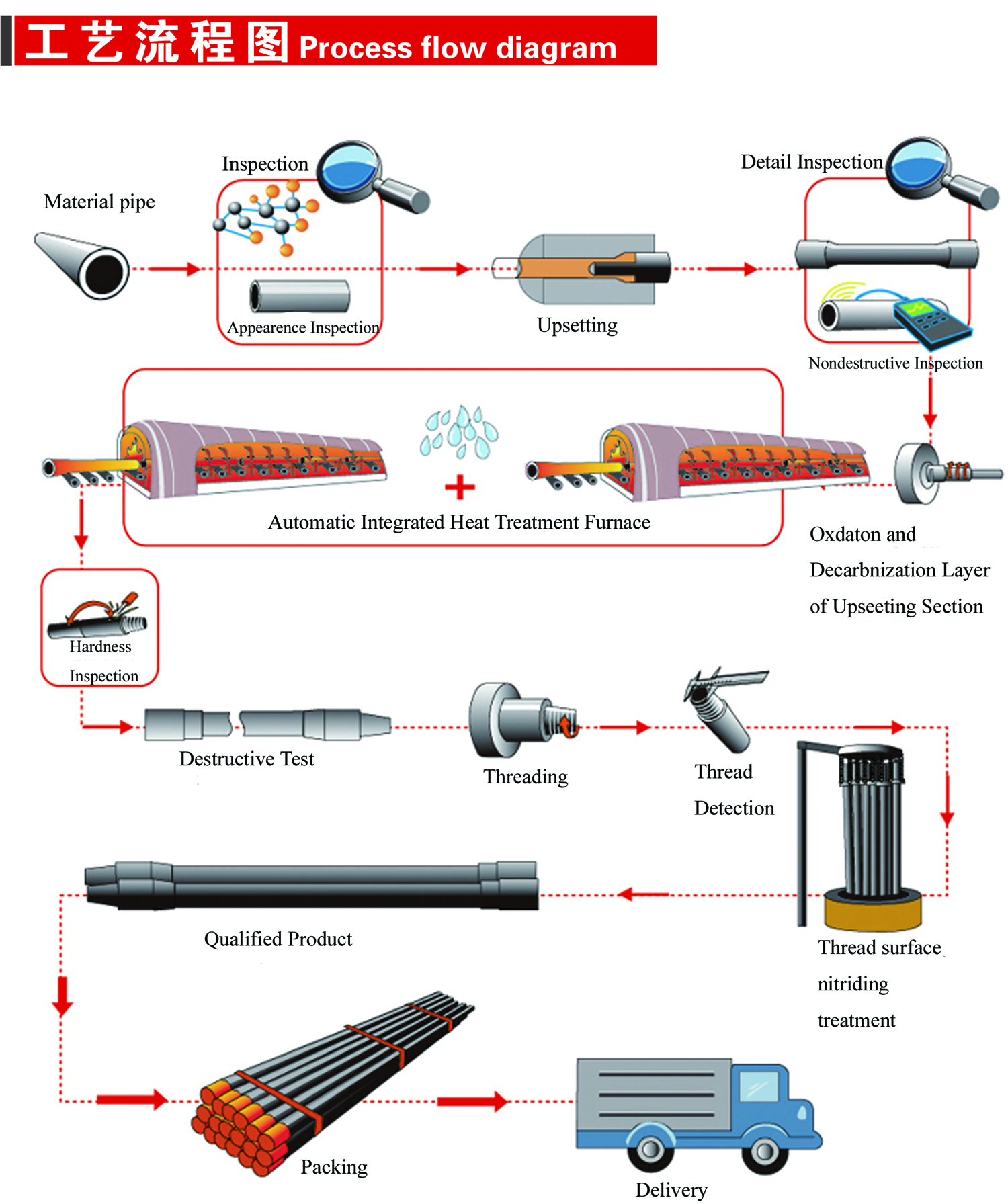
Process
Packing


 English
 Español


 Tel : +86-18565811709
 Email :