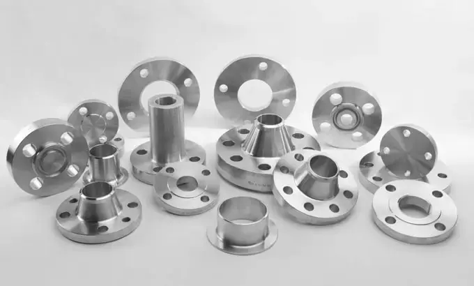
Descripción
Rango de tamaños: 1/2” - 120” (DN 15 - DN 3000)
Clasificación: 150, 300, 400, 600, 900, 1500, 2500; Tipo: Cuello de soldadura, Cuello de soldadura largo, Deslizable, Ciego, Ciego de gafas, Unión traslapada, Soldadura de enchufe, Roscado, Orificio, Brida de unión anular, Espaciador y pieza ciega, Brida de anclaje, Brida API, etc.
Normas: ANSI B16.5, ANSI B16.47 Serie A y Serie B, AWWA C207, BS4504, BS3293, DIN EN1092-1, API590, JIS/KS, ISO 7005-1, JB/T, etc.
Materiales: Acero al carbono, Acero al carbono de baja temperatura, Acero al carbono de alto rendimiento, Material de placa, Acero de baja aleación, Acero inoxidable, Acero inoxidable dúplex.
C.S.: A36, A105, A266 CL2/CL4, ST37.2, C22.8, S235JR, S355JR; LTCS: A350 LF2 CL1/CL2/LF3;
HYCS: A694 F42/F52/F60/F62/F65/F70; Placa: A515 Gr60/70, A516 Gr 60/70, A285 Gr A B C, A240 304, A240 316
LAS: A182 F5, F9, F11 CL1/CL2/CL3, F12 CL1/CL2, F22 CL1/CL3, F91
SS: A182 F304/L, F304H, F316/L, F317/L, F44
SS dúplex: A182 F51/UNS 31803, F53/UNS 32750
Aplicación: Ampliamente utilizado en los sectores de gas, petróleo, tuberías, suministro de agua, electricidad y maquinaria.
Brida de cuello soldable
La brida de cuello soldable cuenta con una extensión de cuello y un bisel soldado. Proporciona una conexión de forma natural, ideal para aplicaciones de alta presión y mayor tamaño.
Brida ciega
Las bridas ciegas no tienen orificio ni diámetro interior. Suelen modificarse para incluir roscas NPT o orificios personalizados para funcionar como bridas deslizantes sin buje.
Brida de unión solapada
Las bridas de unión solapada están diseñadas para encajar sobre un conector de extremo corto. Presentan un buje extendido y un radio mecanizado en la base de la cara plana.
Brida deslizante
La brida deslizante está diseñada para alojar la tubería en el centro/orificio, lo que permite la soldadura alrededor del diámetro exterior de la tubería.
Brida de soldadura a enchufe
Las bridas de soldadura a enchufe tienen un receptáculo para insertar la tubería cuando las limitaciones de espacio dificultan el uso de las bridas de cuello soldado.
Brida roscada
Las bridas roscadas tienen un centro roscado NPT hembra para la conexión a tuberías con rosca macho.
Especificación
|
CLASS 150 According to ASTM A/SA-105; ANSI B16.5
|
|
Nominal
Pipe
Size
|
Outside
Diam. of
Flange (O)
|
Thick.
of
Flange (C)
|
Diam.
of
Raised Face (R)
|
Diam.
of Hub
at Base (X)
|
Length
thru Hub
(Y)
|
Min.
Thread
Length
(T)
|
Min.
Counter
Bore (Q)
|
No. of
Holes
|
Diam. of
Holes
|
Diam. of
Bolts
|
Diam.
of Bolt
Circle
|
Approx.
Weight
(in Pounds)
|
|
½
|
3.5
|
0.44
|
1.38
|
1.19
|
0.62
|
0.62
|
—
|
4
|
0.62
|
0.5
|
2.38
|
1
|
|
¾
|
3.88
|
0.5
|
1.69
|
1.5
|
0.62
|
0.62
|
—
|
4
|
0.62
|
0.5
|
2.75
|
2
|
|
1
|
4.25
|
0.56
|
2
|
1.94
|
0.69
|
0.69
|
—
|
4
|
0.62
|
0.5
|
3.12
|
2
|
|
1 ¼
|
4.62
|
0.62
|
2.5
|
2.31
|
0.81
|
0.81
|
—
|
4
|
0.62
|
0.5
|
3.5
|
3
|
|
1 ½
|
5
|
0.69
|
2.88
|
2.56
|
0.88
|
0.88
|
—
|
4
|
0.62
|
0.5
|
3.88
|
3
|
|
2
|
6
|
0.75
|
3.62
|
3.06
|
1
|
1
|
—
|
4
|
0.75
|
0.62
|
4.75
|
5
|
|
2 ½
|
7
|
0.88
|
4.12
|
3.56
|
1.12
|
1.12
|
—
|
4
|
0.75
|
0.62
|
5.5
|
7
|
|
3
|
7.5
|
0.94
|
5
|
4.25
|
1.19
|
1.19
|
—
|
4
|
0.75
|
0.62
|
6
|
8
|
|
3 ½
|
8.5
|
0.94
|
5.5
|
4.81
|
1.25
|
1.25
|
—
|
8
|
0.75
|
0.62
|
7
|
11
|
|
4
|
9
|
0.94
|
6.19
|
5.31
|
1.31
|
1.31
|
—
|
8
|
0.75
|
0.62
|
7.5
|
13
|
|
5
|
10
|
0.94
|
7.31
|
6.44
|
1.44
|
1.44
|
—
|
8
|
0.88
|
0.75
|
8.5
|
15
|
|
6
|
11
|
1
|
8.5
|
7.56
|
1.56
|
1.56
|
—
|
8
|
0.88
|
0.75
|
9.5
|
19
|
|
8
|
13.5
|
1.12
|
10.62
|
9.69
|
1.75
|
1.75
|
—
|
8
|
0.88
|
0.75
|
11.75
|
30
|
|
10
|
16
|
1.19
|
12.75
|
12
|
1.94
|
1.94
|
—
|
12
|
1
|
0.88
|
14.25
|
43
|
|
12
|
19
|
1.25
|
15
|
14.38
|
2.19
|
2.19
|
—
|
12
|
1
|
0.88
|
17
|
64
|
|
14
|
21
|
1.38
|
16.25
|
15.75
|
2.25
|
2.25
|
—
|
12
|
1.12
|
1
|
18.75
|
90
|
|
16
|
23.5
|
1.44
|
18.5
|
18
|
2.5
|
2.5
|
—
|
16
|
1.12
|
1
|
21.25
|
98
|
|
18
|
25
|
1.56
|
21
|
19.88
|
2.69
|
2.69
|
—
|
16
|
1.25
|
1.13
|
22.75
|
130
|
|
20
|
27.5
|
1.69
|
23
|
22
|
2.88
|
2.88
|
—
|
20
|
1.25
|
1.12
|
25
|
165
|
|
24
|
32
|
1.88
|
27.25
|
26.12
|
3.25
|
3.25
|
—
|
20
|
1.38
|
1.25
|
29.5
|
220
|
|
CLASS 300 According to ASTM A/SA-105; ANSI B16.5
|
|
Nominal
Pipe
Size
|
Outside
Diam. of
Flange (O)
|
Thick.
of
Flange (C)
|
Diam.
of
Raised Face
(R)
|
Diam.
of Hub
at Base
(X)
|
Length
thru Hub
(Y)
|
Min.
Thread
Length
(T)
|
Min.
Counter Bore
(Q)
|
No. of
Holes
|
Diam. of
Holes
|
Diam.
of Bolts
|
Diam.
of Bolt
Circle
|
Approx.
Weight
(in Pounds)
|
|
1/2
|
3.75
|
0.56
|
1.38
|
1.5
|
0.88
|
0.62
|
0.93
|
4
|
0.62
|
0.5
|
2.62
|
2
|
|
3/4
|
4.62
|
0.62
|
1.69
|
1.88
|
1
|
0.62
|
1.14
|
4
|
0.75
|
0.62
|
3.25
|
3
|
|
1
|
4.88
|
0.69
|
2
|
2.12
|
1.06
|
0.69
|
1.41
|
4
|
0.75
|
0.62
|
3.5
|
3
|
|
1 1/4
|
5.25
|
0.75
|
2.5
|
2.5
|
1.06
|
0.81
|
1.75
|
4
|
0.75
|
0.62
|
3.88
|
4
|
|
1 1/2
|
6.12
|
0.81
|
2.88
|
2.75
|
1.19
|
0.88
|
1.99
|
4
|
0.88
|
0.75
|
4.5
|
6
|
|
2
|
6.5
|
0.88
|
3.62
|
3.31
|
1.31
|
1.12
|
2.5
|
8
|
0.75
|
0.62
|
5
|
7
|
|
2 1/2
|
7.5
|
1
|
4.12
|
3.94
|
1.5
|
1.25
|
3
|
8
|
0.88
|
0.75
|
5.88
|
10
|
|
3
|
8.25
|
1.12
|
5
|
4.62
|
1.69
|
1.25
|
3.63
|
8
|
0.88
|
0.75
|
6.62
|
13
|
|
3 1/2
|
9
|
1.19
|
5.5
|
5.25
|
1.75
|
1.44
|
4.13
|
8
|
0.88
|
0.75
|
7.25
|
17
|
|
4
|
10
|
1.25
|
6.19
|
5.75
|
1.88
|
1.44
|
4.63
|
8
|
0.88
|
0.75
|
7.88
|
22
|
|
5
|
11
|
1.38
|
7.31
|
7
|
2
|
1.69
|
5.69
|
8
|
0.88
|
0.75
|
9.25
|
28
|
|
6
|
12.5
|
1.44
|
8.5
|
8.12
|
2.06
|
1.81
|
6.75
|
12
|
0.88
|
0.75
|
10.62
|
39
|
|
8
|
15
|
1.62
|
10.62
|
10.25
|
2.44
|
2
|
8.75
|
12
|
1
|
0.88
|
13
|
58
|
|
10
|
17.5
|
1.88
|
12.75
|
12.62
|
2.62
|
2.19
|
10.88
|
16
|
1.12
|
1
|
15.25
|
81
|
|
12
|
20.5
|
2
|
15
|
14.75
|
2.88
|
2.38
|
12.94
|
16
|
1.25
|
1.12
|
17.75
|
115
|
|
14
|
23
|
2.12
|
16.25
|
16.75
|
3
|
2.5
|
14.19
|
20
|
1.25
|
1.12
|
20.25
|
165
|
|
16
|
25.5
|
2.25
|
18.5
|
19
|
3.25
|
2.69
|
16.19
|
20
|
1.38
|
1.25
|
22.5
|
190
|
|
18
|
28
|
2.38
|
21
|
21
|
3.5
|
2.75
|
18.19
|
24
|
1.38
|
1.25
|
24.75
|
250
|
|
20
|
30.5
|
2.5
|
23
|
23.12
|
3.75
|
2.88
|
20.19
|
24
|
1.38
|
1.25
|
27
|
315
|
|
24
|
36
|
2.75
|
27.25
|
27.62
|
4.19
|
3.25
|
24.19
|
24
|
1.62
|
1.5
|
32
|
475
|
|
CLASS 600 According to ASTM A/SA-105; ANSI B16.5
|
|
Nominal
Pipe
Size
|
Outside
Diam. of
Flange (O)
|
Thick.
of
Flange
(C)
|
Diam.
of
Raised Face
(R)
|
Diam.
of Hub
at Base (X)
|
Length
thru Hub
(Y)
|
Min.
Thread
Length
(T)
|
Min.
Counter
Bore
(Q)
|
No. of
Holes
|
Diam. of
Holes
|
Diam. of
Bolts
|
Diam. of
Bolt Circle
|
Approx.
Weight
(in Pounds)
|
|
1/2
|
3.75
|
0.56
|
1.38
|
1.5
|
0.88
|
0.62
|
0.93
|
4
|
0.62
|
0.5
|
2.62
|
2
|
|
3/4
|
4.62
|
0.62
|
1.69
|
1.88
|
1
|
0.62
|
1.14
|
4
|
0.75
|
0.62
|
3.25
|
3
|
|
1
|
4.88
|
0.69
|
2
|
2.12
|
1.06
|
0.69
|
1.41
|
4
|
0.75
|
0.62
|
3.5
|
4
|
|
1 1/4
|
5.25
|
0.81
|
2.5
|
2.5
|
1.12
|
0.81
|
1.75
|
4
|
0.75
|
0.62
|
3.88
|
5
|
|
1 1/2
|
6.12
|
0.88
|
2.88
|
2.75
|
1.25
|
0.88
|
1.99
|
4
|
0.88
|
0.75
|
4.5
|
7
|
|
2
|
6.5
|
1
|
3.62
|
3.31
|
1.44
|
1.12
|
2.5
|
8
|
0.75
|
0.62
|
5
|
9
|
|
2 1/2
|
7.5
|
1.12
|
4.12
|
3.94
|
1.62
|
1.25
|
3
|
8
|
0.88
|
0.75
|
5.88
|
13
|
|
3
|
8.25
|
1.25
|
5
|
4.62
|
1.81
|
1.38
|
3.63
|
8
|
0.88
|
0.75
|
6.62
|
16
|
|
3 1/2
|
9
|
1.38
|
5.5
|
5.25
|
1.94
|
1.56
|
4.13
|
8
|
1
|
0.88
|
7.25
|
21
|
|
4
|
10.75
|
1.5
|
6.19
|
6
|
2.12
|
1.62
|
4.63
|
8
|
1
|
0.88
|
8.5
|
37
|
|
5
|
13
|
1.75
|
7.31
|
7.44
|
2.38
|
1.88
|
5.69
|
8
|
1.12
|
1
|
10.5
|
63
|
|
6
|
14
|
1.88
|
8.5
|
8.75
|
2.62
|
2
|
6.75
|
12
|
1.12
|
1
|
11.5
|
80
|
|
8
|
16.5
|
2.19
|
10.62
|
10.75
|
3
|
2.25
|
8.75
|
12
|
1.25
|
1.12
|
13.75
|
115
|
|
10
|
20
|
2.5
|
12.75
|
13.5
|
3.38
|
2.56
|
10.88
|
16
|
1.38
|
1.25
|
17
|
170
|
|
12
|
22
|
2.62
|
15
|
15.75
|
3.62
|
2.75
|
12.94
|
20
|
1.38
|
1.25
|
19.25
|
200
|
|
14
|
23.75
|
2.75
|
16.25
|
17
|
3.69
|
2.88
|
14.19
|
20
|
1.5
|
1.38
|
20.75
|
230
|
|
16
|
27
|
3
|
18.5
|
19.5
|
4.19
|
3.06
|
16.19
|
20
|
1.62
|
1.5
|
23.75
|
330
|
|
18
|
29.25
|
3.25
|
21
|
21.5
|
4.62
|
3.12
|
18.19
|
20
|
1.75
|
1.63
|
25.75
|
400
|
|
20
|
32
|
3.5
|
23
|
24
|
5
|
3.25
|
20.19
|
24
|
1.75
|
1.62
|
28.5
|
510
|
|
24
|
37
|
4
|
27.25
|
28.25
|
5.5
|
3.62
|
24.19
|
24
|
2
|
1.88
|
33
|
730
|
|
CLASS 900According to ASTM A/SA-105; ANSI B16.5
|
|
Nominal
Pipe
Size
|
Outside
Diam. of
Flange (O)
|
Thick.
of
Flange
(C)
|
Diam.
of
Raised Face
(R)
|
Diam.
of Hub
at Base
(X)
|
Length
thru Hub (Y)
|
Min.
Thread
Length
(T)
|
Min.
Counter
Bore
(Q)
|
No. of
Holes
|
Diam. of
Holes
|
Diam. of
Bolts
|
Diam. of
Bolt Circle
|
Approx.
Weight
(in Pounds)
|
|
1/2
|
4.75
|
0.88
|
1.38
|
1.5
|
1.25
|
0.88
|
0.93
|
4
|
0.88
|
0.75
|
3.25
|
4
|
|
3/4
|
5.12
|
1
|
1.69
|
1.75
|
1.38
|
1
|
1.14
|
4
|
0.88
|
0.75
|
3.5
|
5
|
|
1
|
5.88
|
1.12
|
2
|
2.06
|
1.62
|
1.12
|
1.41
|
4
|
1
|
0.88
|
4
|
8
|
|
1 1/4
|
6.25
|
1.12
|
2.5
|
2.5
|
1.62
|
1.19
|
1.75
|
4
|
1
|
0.88
|
4.38
|
9
|
|
1 1/2
|
7
|
1.25
|
2.88
|
2.75
|
1.75
|
1.25
|
1.99
|
4
|
1.12
|
1
|
4.88
|
12
|
|
2
|
8.5
|
1.5
|
3.62
|
4.12
|
2.25
|
1.5
|
2.5
|
8
|
1
|
0.88
|
6.5
|
25
|
|
2 1/2
|
9.62
|
1.62
|
4.12
|
4.88
|
2.5
|
1.88
|
3
|
8
|
1.12
|
1
|
7.5
|
36
|
|
3
|
9.5
|
1.5
|
5
|
5
|
2.12
|
1.62
|
3.63
|
8
|
1
|
0.88
|
7.5
|
26
|
|
4
|
11.5
|
1.75
|
6.19
|
6.25
|
2.75
|
1.88
|
4.63
|
8
|
1.25
|
1.12
|
9.25
|
53
|
|
5
|
13.75
|
2
|
7.31
|
7.5
|
3.12
|
2.12
|
5.69
|
8
|
1.38
|
1.25
|
11
|
83
|
|
6
|
15
|
2.19
|
8.5
|
9.25
|
3.38
|
2.25
|
6.75
|
12
|
1.25
|
1.12
|
12.5
|
110
|
|
8
|
18.5
|
2.5
|
10.62
|
11.75
|
4.00
|
2.50
|
8.75
|
12
|
1.5
|
1.38
|
15.5
|
170
|
|
10
|
21.5
|
2.75
|
12.75
|
14.5
|
4.25
|
2.81
|
10.88
|
16
|
1.5
|
1.38
|
18.5
|
245
|
|
12
|
24
|
3.12
|
15
|
16.5
|
4.62
|
3
|
12.94
|
20
|
1.5
|
1.38
|
21
|
325
|
|
14
|
25.25
|
3.38
|
16.25
|
17.75
|
5.12
|
3.25
|
14.19
|
20
|
1.62
|
1.5
|
22
|
400
|
|
16
|
27.75
|
3.5
|
18.5
|
20
|
5.25
|
3.38
|
16.19
|
20
|
1.75
|
1.63
|
24.25
|
425
|
|
18
|
31
|
4
|
21
|
22.25
|
6
|
3.5
|
18.19
|
20
|
2
|
1.88
|
27
|
600
|
|
20
|
33.75
|
4.25
|
23
|
24.5
|
6.25
|
3.62
|
20.19
|
20
|
2.12
|
2
|
29.5
|
730
|
|
24
|
41
|
5.5
|
27.25
|
29.5
|
8
|
4
|
24.19
|
20
|
2.62
|
2.5
|
35.5
|
1400
|
|
CLASS 1500 According to ASTM A/SA-105; ANSI B16.5
|
|
Nominal
Pipe
Size
|
Outside
Diam. of
Flange (O)
|
Thick.
of
Flange
(C)
|
Diam.
of
Raised Face
(R)
|
Diam.
of Hub
at Base
(X)
|
Length
thru Hub
(Y)
|
Min.
Thread
Length
(T)
|
Min.
Counter
Bore
(Q)
|
No. of
Holes
|
Diam. of
Holes
|
Diam. of
Bolts
|
Diam. of
Bolt Circle
|
Approx.
Weight
(in Pounds)
|
|
1/2
|
4.75
|
0.88
|
1.38
|
1.5
|
1.25
|
0.88
|
0.93
|
4
|
0.88
|
0.75
|
3.25
|
4
|
|
3/4
|
5.12
|
1
|
1.69
|
1.75
|
1.38
|
1
|
1.14
|
4
|
0.88
|
0.75
|
3.5
|
5
|
|
1
|
5.88
|
1.12
|
2
|
2.06
|
1.62
|
1.12
|
1.41
|
4
|
1
|
0.88
|
4
|
8
|
|
1 1/4
|
6.25
|
1.12
|
2.5
|
2.5
|
1.62
|
1.19
|
1.75
|
4
|
1
|
0.88
|
4.38
|
9
|
|
1 1/2
|
7
|
1.25
|
2.88
|
2.75
|
1.75
|
1.25
|
1.99
|
4
|
1.12
|
1
|
4.88
|
12
|
|
2
|
8.5
|
1.5
|
3.62
|
4.12
|
2.25
|
1.5
|
2.5
|
8
|
1
|
0.88
|
6.5
|
25
|
|
2 1/2
|
9.62
|
1.62
|
4.12
|
4.88
|
2.5
|
1.88
|
3
|
8
|
1.12
|
1
|
7.5
|
36
|
Estándar
|
Standard
|
Specification
|
|
ASTM A105
|
Standard Specification for Carbon Steel Forgings for Piping Applications
|
|
ASTM A350
|
Standard Specification for Carbon and Low-Alloy Steel Forgings, Requiring Notch Toughness Testing for Piping Components
|
|
ASTM A182
|
Standard Specification for Forged or Rolled Alloy and Stainless Steel Pipe Flanges, Forged Fittings, and Valves and Parts for High-Temperature Service
|
|
ASTM A404
|
Specification for Forged or Rolled Alloy Steel Pip Flanges, Forged Fittings, and Valves and Parts Specially Heat Treated for High-Temperature Service (Withdrawn 1974)
|
|
ASTM A234
|
Standard Specification for Piping Fittings of Wrought Carbon Steel and Alloy Steel for Moderate and High Temperature Service
|
|
ASTM A420
|
Standard Specification for Piping Fittings of Wrought Carbon Steel and Alloy Steel for Low-Temperature Service
|
|
ASTM A403
|
Standard Specification for Wrought Austenitic Stainless Steel Piping Fittings
|
|
ASTM A694
|
Standard Specification for Carbon and Alloy Steel Forgings for Pipe Flanges, Fittings, Valves, and Parts for High-Pressure Transmission Service
|
Proceso
Embalaje


 English
 Español


 Tel : +86-0731-85648266
 Correo electrónico :